|
DIRECT STEERING:
Materials:
Two 2-56 screws (or one long one), 2-56 drill bit & tap, 2-56
partially threaded rod, Dubro Over-Ride Servo Saver #120, Dubro Swivel Ball Link 2-56 w/Hardware #367.
Instructions:
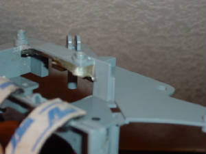
1)
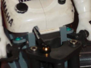
First you have to lock the steering head in the vertical position. Remove the 2.6mm screw, spring, and horn that hold the
backside steering head together and drill a 2-56 hole straight down through the front of the steering head. Tap the holes
on both the top side and bottom side (or just once if your tap is long enough) with 2-56 and thread a screw into the top and
bottom (or one long one through
the top). Dremel the frame so that the bottom screw head can fit. Many people before have
glued in a pin through the hole to hold the steering head but with the screws they can easily be taken out and converted to
stock steering again.
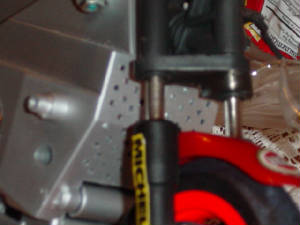
2) Next make a 2-56 hole on the top triple clamp on the right side, halfway between the pivot and
right screw, and tap the hole. This position is such that the control rod doesn't foul on the front tank latch on the frame
(if it turns out it does foul a bit then dremel some of it off).
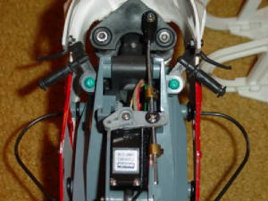
3) Then power up the steering servo and center the steering.
Mount the servo horn on at a 90 degree angle and drill a small hole on it (if one is not there because I actually used a HOR
servo) for the Dubro servo saver slider such that it is somewhat inline with the hole you made in the top triple clamp. Be
careful though because if
the hole is too close to the servo the slider will foul on the servo case. Fit the slider upside
down and make sure it can easily rotate. Then rigidly mount the servo in a laid down position in the frame, making sure that
it is high enough so that the slider doesn't hit the frame.
4) Finally the control rod. Take the ball link and cut half
of the end off of it so that it won't foul on the frame. Then install the threaded end of the rod into the link. Mine didn't
thread in that deep so I drilled into the link to make the engagement length longer. After that, give it a slight bend angle
upwards right on the end and use the hardware to attach the link to the top triple clamp. Next,
from the Dubro servo saver
package, slide onto the opposite end of the shaft in this order: collet, spring, slider, spring, and then collet. Mount the
slider into the servo horn hole you made earlier and secure it with the included hardware. Center the triple clamp and then
tighten up the collets so that there is even space between the collets and that the springs have no preload. Then when you
have it
all in place, cut off the excess rod and you're done! Note: in order to fit on the tank you must make a hole on
the right side for control arm clearance.
Driving:
First make sure channel one is reversed on your radio. Check that
when you turn the stick left, the triples turn right and vice versa. Then take it out for a spin! What you'll notice is the
ultra fast and ultra smooth responsiveness of direct steering.
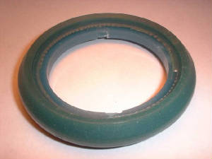
FRONT SILICONE INSERTS:
Jimmy from rcgroups makes and sells these! Email him - akura22000@yahoo.com.
By using the stock “swivel” steering method the bike will be very slow to react
to driver input because you are essentially running on a flat front tire. To properly simulate air pressure for the Kyosho
tires, mold an insert out of silicone. The difference in handling is like night and day.
Materials: OOMOO 25 two-part silicone mold making rubber from smooth-on.com (or art store),
vaseline, kit front rim, kit front tire (after this procedure it cannot be used for running), flywheel (optional), syringe
to inject silicone, x-acto knife.
1) Coat the inside of the front
tire with a thin layer of vaseline to prevent the silicone from sticking.
2) Assemble the front tire
to the front rim and use an x-acto knife to cutout a small hole for the syringe to fit in. Using the flywheel is optional
(different handling characteristics with this).
3) Mix the two-part silicone
1:1 as per the instructions, place into syringe, and inject into the tire hole until it is COMPLETELY full. In fact, overfill
it to make sure. Allow to sit overnight.
4) Carefully peel the
insert off the rim and use the x-acto knife to trim off the excess flashing. Then install onto clean rim and tire, making
sure that the insert sits correctly and evenly. Done!
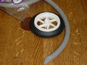
REAR TIRE INSERTS:
Despite the kit coming with none
whatsoever we recommend you put some decent foam inserts in the rear tires. Inserts come with the Kyosho high grip tire set
#GPW14, but these are way too soft. For a more consistent rear bite try using ½”D round foam backer rod from your local
hardware store. Cut the ends at an angle and fit it into the rear tire. Also you can use rubber cement to glue the ends of
the foam together, but if you press fit the foam snug tight then don’t worry about it. Same can also be done to the
HOR bike.
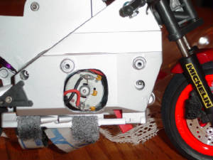
LARGER MOTORS:
With the thin design of the Mark
1 chassis, motors larger than the 180-size kit and ball bearing option motors don’t fit. That’s because the endbell
of the larger motors are longer in length. The only way around this is to dremel out a large hole on the right side of the
chassis. Make sure that the hole is big enough to allow the gearbox to slide and adjust chain tension. Also, in order to mount
the larger motors onto the gearbox, you must drill holes to match the bolting pattern. Pictured here is a Speed 300 motor.
MOTOR VENTS:
Along with larger
motors you should also drill holes in the chassis around the radiator section so that they have enough natural air cooling.
This will increase the life of your motor.
EPOXY CRASH BAR MOUNTS:
These sections handle the most shock from crashes and should be reinforced,
especially at the rear left hole because there is barely any supporting material. Follow the instructions as described in
the HOR section.
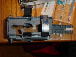
BATTERY TRAY:
The routing of battery wires can be a bit awkward for the static bike. To
make it easier and also create better access to the electronics, dremel out some of the battery tray so you can easily fish
out the battery plug leads from the ESC. Same can also be done to the HOR bike.
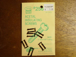
WINDSHIELD:
Also, in high speed crashes the
windshield is likely to crack off because of the thin sections held by the screws. Consider replacing these two metal screws
with 2-56 plastic acetal screws and nuts from your local model train hobby shop so in a crash they break off instead,
keeping the windshield intact. Same can also be done to the HOR bike.
SECURE RIDER:
In addition to the Velcro on the seat, another way to help secure the rider to
the tank is to wrap a ziptie around each of his wrists to the handle bars. This should keep him on no matter what happens
to the bike. Kind of like a seatbelt. Not recommended for riding your real 1:1 bikes.
Last updated: 3/14/06
|