|
|
 |
|
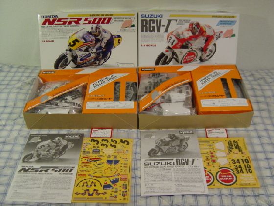
The hanging on rider bike, otherwise known as the HOR, active rider, and Mark 2 (German for version 2), was introduced
by Kyosho in 1992. In four years time, Kyosho completely redesigned the Mark 1 frame to closely resemble that of a real 500cc
GP bike - complete with USD forks, a radiator cover, and a compact gearbox. However the absolute genius of their new
design was that the rider was jointed at the shoulders, hips, arms, and knees and moved in snyc w/steering (hence, the
rider "hangs on" while turning). The HOR comes in two different versions - 1992 Lucky Strike Suzuki Kevin Schwantz
or Doug Chandler body/paint scheme and 1991 Rothmans Honda Wayne Gardner or Mick Doohan body/paint scheme.
INFO GUIDES:
Ian's HOR hopup guide rev8 - 4.7MB (updated 9/17/05)
CLEAN SURFACE:
I think that most "Kyosho riders" would agree that using
a broom (or your hands) to sweep away debris and rocks from your bike's eventual track path is the best modification you can
do to prevent a majority of the crashes that happen with the smaller 1/8th scale bikes. Since they are made mostly from plastic,
any rocks that happen to cross under the front wheel tend to do very bad things! Do you and your bike a favor and scan the
surface everytime before you run.
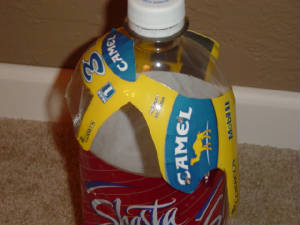
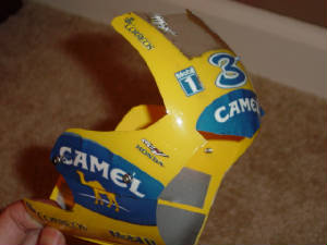
LEXAN FRONT FAIRING:
Advantage to the lexan front fairing is that it is lighter, easier
to paint, and also more resistant to chips since the paint is on the inside. Materials needed: 3 liter clear soda bottle,
Kyosho plastic fairing, permanent marker, lexan curved scissors, hair dryer, hole reamer, lexan paint.
1) Rinse out the bottle and cut off the top and bottom. Cut right down
one side so you have a curve sheet of lexan.
2) Shape the top curved part of the bottle onto the
Kyosho fairing and use the marker to trace the shape. It's hard to do both halves so I usually trace the top half and
do the lower half later (with plenty of overlap).
3) Cut it out and align with the fairing. I usually leave the shape
as is but you can use a heat gun to conform more to the Kyosho shape.
4) Line the fairing up with your modded frame and punch holes for the
crash bar mounts. Paint the inside with lexan paint.
5) Cut a line on the bottom of the lower fairing for
easier battery replacement. Line the insides with tape to protect the paint from scratching on the frame.
ADJUSTABLE
& REPLACEABLE CRASH BARS:
The
crash bars are one of the most important components of an R/C bike. Too long and you won’t be able to lean the bike
over as much and carry any corner speed, while too short the fairing will scrape against the ground and you risk not being
able to get your bike back up from a full lean! The problem with the stock crash bars for the HOR is the latter. Many options
to fix this – bending the crash bars downwards, increasing the front fork length to increase ride height, running w/o
the fairing, etc., but this mod will allow you to setup the lean angle to your liking. Can also be used on the Mark 1 bike.
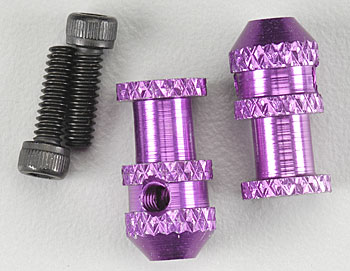
Materials
needed: Set of four metal setscrew wing mounts (Trinity makes them, search "wing mount" on towerhobbies.com), 0.078”
dia. music wire, four long 4-40 steel setscrews, threadlock.
1. First do the crash bar mount area mod listed above. This gives you fresh 4-40 tapped
holes.
2. Take the setscrews and thread lock them
into the wing mount. Try to leave around 3/8"-1/2" of setscrew exposed. Let it dry, then thread them into each hole of the
frame (w/fairing attached).
3. Now for the tricky part – using a
vice, pliers, a curved surface, and a cutter, size two crash bars keeping in mind the distance between the couplers and also
how far the bar sticks out. Make sure the tip of the crash bar is not pointed. You don't have to make it curved, it can be
a U shape with three straight edges. I like it curved however so you can easily slide on a nylon cylinder on it and CA glue
it in place.
4. Next put them snugly into the mounts, tighten
the setscrews, and check your angle of lean. If something is touching the ground, chances are it will catch as you ride the
bike. Shorten/make new ones/bend them down as necessary.
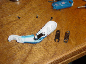
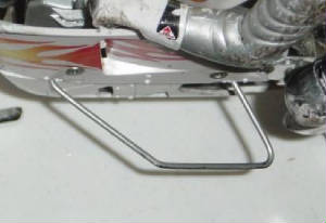
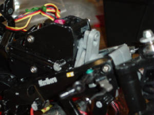
5.
Another way to
make the crash bars are to bend the music wire into the same shape as the stock ones, but longer. A bit tougher but it works.
See pic #2.
|
|
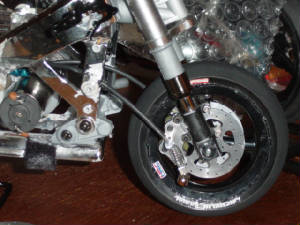
FRONT BRAKES:
Thanks to Pat of the rcgroups forum, functional dual disc
front brakes now exist for the Kyosho bikes. They are actuated by a micro servo in the chassis and brake cables that squeeze
the small brake pads onto the discs. Nice work Pat!! To buy them, click on the link below and send a request to
Pat.

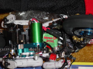
BRUSHLESS MOTOR SYSTEMS:
For maximum power, top speed, and run time, with low maintenance
and in a compact design, try installing the latest brushless motor systems out there. Before they were only available for
small airplanes (no brakes) but now there are many decent controllers out there (w/fully proportional brakes) for cars such
as the Mini-T and HPI Micro RS4. Pictured here is the Mamba 6800Kv brushless system. Can also be used on the Mark 1 bike.
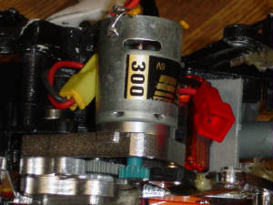
SPEED 300 SIZED MOTORS:
For those of you considering the Speed 300, you should know that
the hole pattern doesn't fit into the gearbox! Actually it is a bit wider than what is provided. You have two options, either
drill the wider holes in the gearbox (plastic or alum. gearboxes) or get an adapter that makes the holes closer together.
Can also be used on the Mark 1 bike.
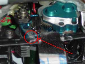
EASIER PINION SERVICE:
The gearboxes look realistic but for tightening and swapping setscrew-type
motor pinions, they're not very good because there's no room for your allen wrench. Take a dremel and carve out a slot on
the lower left hand corner of the case and now you have room to servce your pinions.
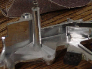
CRASH BAR MOUNT AREA:
When you take a look
at the Mark 2 frame you’ll notice that the backsides of the rear crashbar mounting holes are pretty thin. They break
easily from hard landings, so beefing up this section will definitely save you from buying a replacement frame set. Obviously
you could beef up the whole frame but these sections are most likely to crack (but in addition to the rear mounts I also beef
up the front mounts in the same manner). Can also be used on the Mark 1 bike.
Materials:
sandpaper, 4-40 hex
driver, 4-40 drill and tap, ½” 4-40 hex socket screw x2, transparent tape, Devcon 2-Ton epoxy (2-part w/syringe), dremel
Instructions:
1) Disassemble the frame into halves and scratch off the innersides of the rear crash bar mounts with some sandpaper.
If you’re modifying the chrome plated frame set make sure to get all the chrome off this and the surrounding sections
as well, or else the epoxy won’t stick.
2) Take the 4-40 drill bit and enlarge the mounting hole. Just make one slow pass in and out. Then tap the hole with
4-40 thread all the way through. Thread a fairly long 4-40 hex socket screw all the way into the holes.
3) Tape off the edges of the whole section using transparent tape. This creates a temporary wall that prevents the epoxy
from dripping all over the place.
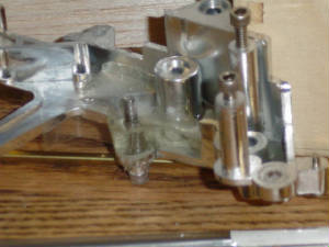
4) Next, pour a small amount of the 2-part epoxy on a disposable plate and mix with the plastic stirrer. With the stirrer,
scoop small amounts of the epoxy onto the backside section until you get about a ¼” of depth.
5) Once you get enough epoxy in there fix the orientation of the frame so that the epoxy pretty much stays in place.
Leave overnight. When you take a look at it again you’ll notice that it is rock hard. Take your hex wrench and slowly
back the screw out. Then remove the tape.
6)
The right side frame is now complete
- for the left side, you must dremel off some epoxy so that the gearbox can easily fit. And that’s it!
UPPER COWLING & LOWER FAIRING:
If you decide to use the kit plastic
front body set you will run into a few problems while running the bikes. First of all, at full lean the bike will drag away
at the lower fairing and scratch up your paint job! Next, with the way the lower fairing snaps into the upper cowling, it
is very easy to come off while running. An easy fix for the two problems is to run without the lower fairing, but if you want
to run with it on try these mods. Can also be used on the Mark 1 bike.
1) Buy some Team Associated clear chassis protector sheet #6312 and cut two 1“x1½” sections. Place them on
each side of the lower front side of the fairing to take up the scratches.
2) Take two short strips of carbon fiber plate (or plastic if convenient) and drill a hole on one end large enough to
fit a 3mm screw, and CA glue a 3mm nut on a side of the hole.
3) Put the side of the hole w/o the nut onto the top cowling (on a flat area) and drill a hole aligned with the screw.
Make sure a short piece of the carbon fiber is trailing off. Then screw it in place with a 3mm screw. This will be the place
where the bottom fairing mounts to the cowling.
4) Attach the lower fairing on and CA glue the trailed off carbon fiber plate onto the fairing.
Now you have a way to secure on the fairing during races!
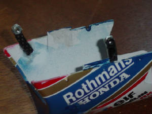
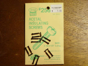
WINDSHIELD:
Also, in high speed crashes the
windshield is likely to crack off because of the thin sections held by the screws. Consider replacing these two metal screws
with 2-56 plastic acetal screws and nuts from your local model train hobby shop so in a crash they break off instead,
keeping the windshield intact. Same can also be done to the Mark 1 bike.
FORK SPACERS:
Depending upon your preference, the front end could use a little bit more height to avoid scratching up the bottom
fairing during cornering at full lean. Try lengthening your front forks by adding in spacers to the top of the forks
before you insert them into the triple clamp assembly. You can also lengthen them a bit more by unscrewing the bottom axle
carriers a little bit from the fork shafts.
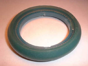
FRONT SILICONE INSERTS:
Jimmy from the rcgroups forum makes and sells these! Email him at akura22000@yahoo.com.
By using the stock “swivel” steering method the bike will be very slow to react
to driver input because you are essentially running on a flat front tire. To properly simulate air pressure for the Kyosho
tires, mold an insert out of silicone. The difference in handling is like night and day.
Materials: OOMOO 25 two-part silicone mold making rubber from smooth-on.com (or art store),
vaseline, kit front rim, kit front tire (after this procedure it cannot be used for running), flywheel (optional), syringe
to inject silicone, x-acto knife.
1) Coat the inside of the front
tire with a thin layer of vaseline to prevent the silicone from sticking.
2) Assemble the front tire
to the front rim and use an x-acto knife to cutout a small hole for the syringe to fit in. Using the flywheel is optional
(different handling characteristics with this).
3) Mix the two-part silicone
1:1 as per the instructions, place into syringe, and inject into the tire hole until it is COMPLETELY full. In fact, overfill
it to make sure. Allow to sit overnight.
4) Carefully peel the
insert off the rim and use the x-acto knife to trim off the excess flashing. Then install onto clean rim and tire, making
sure that the insert sits correctly and evenly. Done!
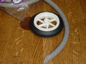
REAR TIRE INSERTS:
Despite the kit coming with none
whatsoever we recommend you put some decent foam inserts in the rear tires. Inserts come with the Kyosho high grip tire set
#GPW14, but these are way too soft. For a more consistent rear bite try using ½”D round foam backer rod from your local
hardware store. Cut the ends at an angle and fit it into the rear tire. Also you can use rubber cement to glue the ends of
the foam together, but if you press fit the foam snug tight then don’t worry about it. Same can also be done to the Mark
1 bike.
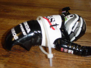
MORE SOLID RIDER:
In some of the more spectacular crashes the top cover of the rider's
back may dislodge and fall off. Before races consider wrapping a zip-tie around the rider's body to prevent this. Then cut
it off before your victory photo shoot!
MORE SOLID ARMS:
This is another one of those convenience/reliability
mods if you plan to race the HORs. This sounds a little funny but when you crash, the arms can dislocate from the elbows!
That's because the loop on the black plastic piece that connects the joint has a slot in it where the arm can dislodge easily.
The way to fix this is to make a similar piece out of carbon fiber sheet (or plastic if convenient) and make it so that the
loops are CLOSED. Then reassemble the arms as usual. Instant fix!
SERVO PIN:
The instruction manual says to install the servo "pin" onto the
servo horn on the innermost hole, but for more response mount the pin on the topmost hole. With the longer torque arm you
get more consistency from your steering servo.
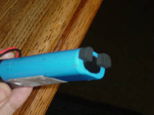
BATTERY PLACEMENT:
Standard 7.2V 6-cell 600mah and 270mah batteries have a small
amount of play when installed into the battery tray. This can cause it to move around a bit and dislodge. Consider attaching
a few pieces of thick foam tape (HPI Part #6273) to the rear ends of your batteries to get rid of the slop. Can also be used
on the Mark 1 bike.
Last updated: 3/14/06
|
|
|
|
|
|
|
|
|
|
|
|

WEBMASTER: Ian Francisco (ianfran@hotmail.com) - "grymg" on rcgroups, yahoo groups, yahoo messenger, etc... WEBMASTER:
2nd Kevin Hicks (kev71h@gmail.com) "Kev71H" on many forums: RCgroups.com
|
|
|
|